How to Create Detailed CAD Drawings for Injection-Molded Parts
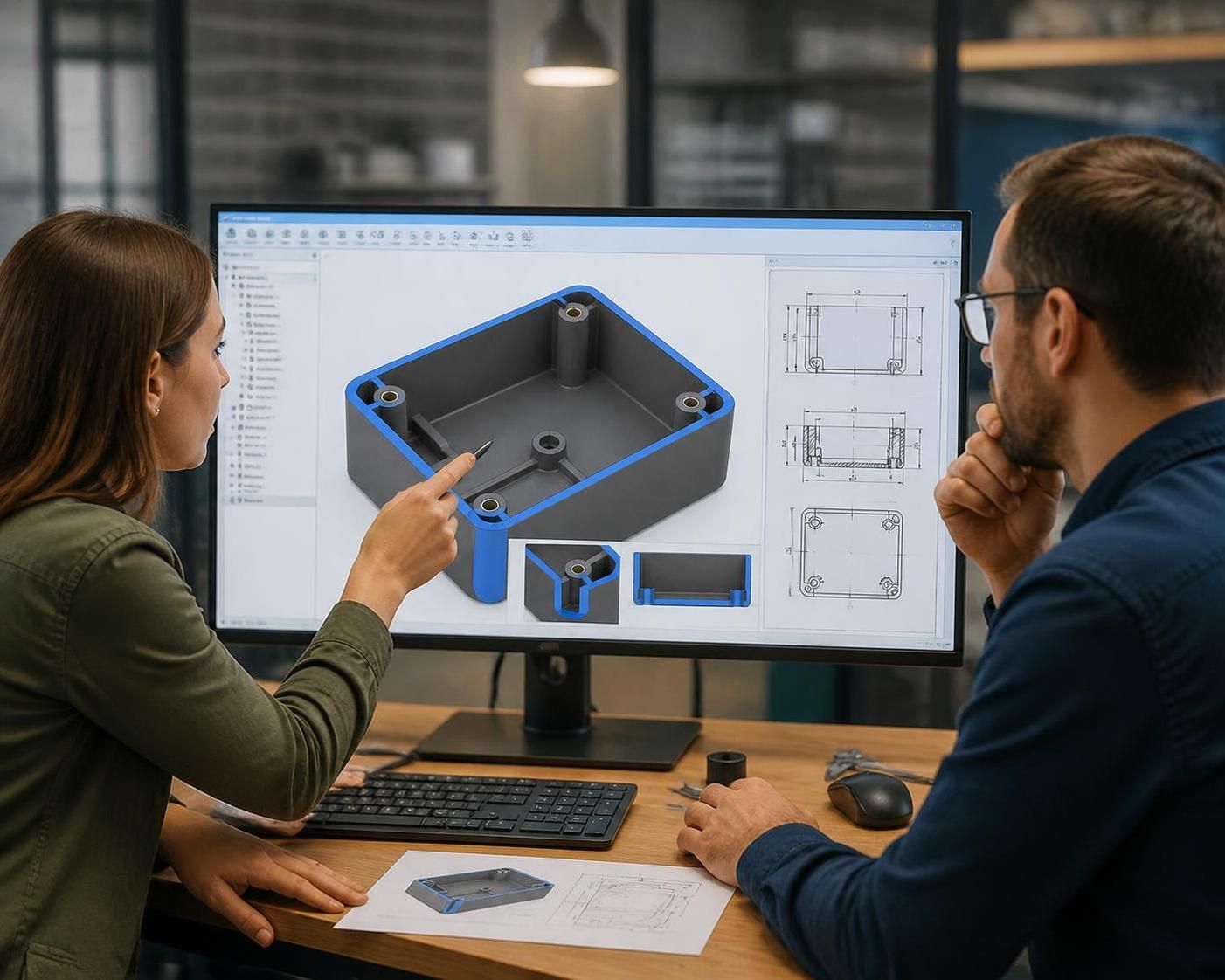
Detailed CAD drawings for injection-molded parts explain the part’s shape, dimensions, material, tolerances, and molding requirements. Creating them carefully helps designers and manufacturers agree on what to make and catch potential problems before tooling begins.
What to Include in the Drawing Package
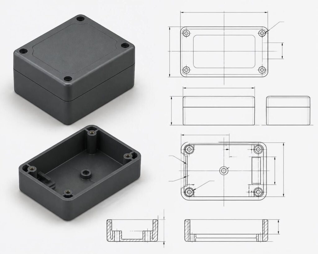
A 3D CAD model shows the part’s form, while 2D drawings communicate measurements and requirements that may not be clear from the model alone. Together, they give the manufacturer a clearer definition of the intended part.
Include:
- Dimensions and tolerances: Define important sizes and how much variation isacceptable. Set tight tolerances only where the part’s fit or function requires them.
- Material: Name the intended resin or material grade when known. Material choiceaffects shrinkage, strength, appearance, and how the part behaves during molding.
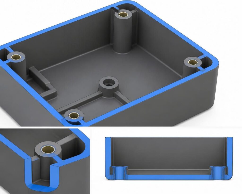
- Wall thickness and features: Call out important wall sections, ribs, bosses, holes, andother functional details.
- Surface and appearance requirements: Identify important cosmetic surfaces, finishes,colors, or areas where marks should be avoided.
- Drawing notes and revision details: State the applicable drawing standard, units,revision, and any special manufacturing or inspection requirements.
The ASME Y14.5 dimensioning and tolerancing standard provides a common framework for communicating geometric dimensions and tolerances. Agree with your manufacturing partner on the standard and version to use. asme.org
Check the Design for Molding
A drawing can be clear and still describe a part that is difficult to mold. Review the geometry with the intended mold-opening direction in mind.
Check that vertical walls have suitable draft, or taper, so the part can release from the mold. The right amount depends on details such as material, wall depth, surface texture, and tooling, so confirm it with your mold maker rather than treating one rule of thumb as universal.
Also look for abrupt changes in wall thickness, sharp internal corners, and bulky sections. These may contribute to uneven cooling or cosmetic defects; the best design choice depends on the part’s function and material. A manufacturer’s design-for-manufacturing (DFM) review can help identify areas to examine before tooling.
A Practical CAD Drawing Workflow
Use this step-by-step process before sending a part for a quote or tooling review:
- Confirm the part’s purpose. Record how it fits with other components, what loads itmust handle, and which surfaces are visible.
- Choose a preliminary material. If you are unsure, ask the manufacturer which optionssuit the part’s needs.
- Build or review the 3D model. Check the overall shape, wall transitions, draft, ribs,bosses, and openings.
- Set critical dimensions and tolerances. Mark the features that affect fit or function,and avoid adding unnecessary precision to noncritical areas.
- Add manufacturing notes. Include material, finish, color, units, revision, and any knowninspection requirements.
- Request a DFM review. Ask the manufacturer to review moldability, dimensions, andany assumptions before the design is released.
- Update and release the files. Apply agreed changes, update the revision, and send themodel and drawing together.
Common Mistakes to Avoid
A few omissions can create confusion or lead to costly changes:
- Leaving out units, material, or revision information.
- Applying tight tolerances to every dimension without a functional reason.
- Forgetting to review draft and part release.
- Sending a 3D model without the 2D dimensions or notes the manufacturer needs.
- Updating the model but not the drawing—or sending files with mismatched revisions.
For dimensioning and tolerancing, use an agreed standard consistently; ASME describes Y14.5 as a guide for communicating and interpreting those requirements. For molding-specific checks, review a practical injection-molding design guide and confirm recommendations with your manufacturer.