Advanced CAD Drawings for Injection Molded Parts and Prototypes
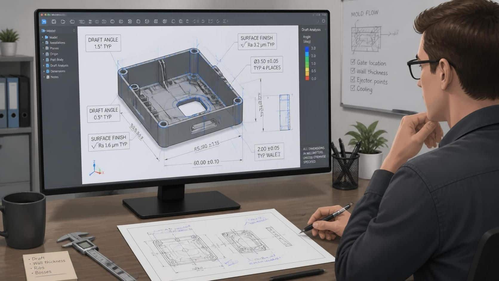
Advanced CAD drawings help you design injection molded parts correctly the first time—so you cut errors, speed up prototyping, and avoid costly mold and fit issues.
What Advanced CAD Drawings Do for Injection Molded Parts
Advanced CAD drawings are the manufacturing blueprint for injection molded parts. They include more than sizes—they also guide tolerances, surface finish, and key mold-ready features.
This detail helps teams build what was intended. It also helps manufacturers plan tooling and machining with fewer surprises.
Why They Matter for Prototypes (and Not Just Final Parts)
Prototypes move faster when the CAD drawing is complete. You can test form, fit, and function using a model that matches production needs.
Advanced drawings also support better reviews across teams. Engineers, designers, and production staff can spot risks before anything is built.
Key Features to Include in Your CAD Drawings
If you want your part to mold reliably, include these essentials in your drawings:
- Draft angles for easier ejection
- Fillets and radii to reduce stress and cracking
- Wall thickness guidance to limit warpage and sink
- Accurate dimensions and tolerances for assembly fit
- Material specification to match strength and flow needs
- Surface finish requirements for performance and appearance
- Gate and runner notes to prevent flow defects
These items reduce guesswork on the shop floor. They also help avoid redesigns after first samples.
Common Mistakes That Cause Mold and Prototype Failures
Even strong designs can fail if the drawing misses mold basics. Here are frequent problems to avoid:
- Not enough draft (the part won’t eject cleanly)
- Sharp corners (stress builds and cracks become more likely)
- Non-uniform wall thickness (uneven cooling leads to warping)
- Undercuts (mold removal gets harder and more expensive)
- Poor gate placement (flow issues can cause defects)
A good drawing prevents “assumption work.” It turns the build into a clear, repeatable process.
Step-by-Step Workflow to Create Better CAD Drawings
Use this simple workflow to make your drawings actionable for injection molding:
- Start with design for manufacturing goals
- Lock draft, fillets, and realistic wall thickness early.
- Define all critical dimensions and tolerances
- Add tolerance notes only where function needs it.
- Add material and finish requirements
- Specify resin type and the surface finish level needed.
- Mark assembly features clearly
- Show mating surfaces, bosses, snaps, and alignment needs.
- Plan gating and flow guidance
- Include gate expectations so the mold maker can design correctly.
- Run a quick design review
- Check for undercuts, thin sections, and sharp transitions.
- Prepare prototype-ready drawing packages
- Include the notes your manufacturer needs for sampling.
This workflow keeps everyone aligned from concept to first article.
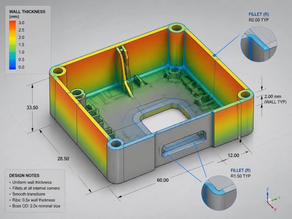

How CAD Helps With Complex Geometries
Complex geometry is where advanced CAD pays off most. You can design shapes that reduce weight, guide flow, or improve performance.
CAD also helps you plan for defect risks like warping and sink marks. When teams review the model early, they can adjust geometry before prototype time is wasted.
For mold and part design guidance, it helps to use reputable references. For example, understanding injection molding basics and common design considerations can be supported by industry sources like:
Best Practices for Drawing Clarity (So No One Misreads It)
A “correct” drawing is also an easy-to-follow drawing. Keep file structure organized and make the intent obvious.
Do this to reduce delays:
- Use consistent naming for parts and drawing layers
- Group features logically in assemblies
- Add notes for material, process, and special requirements
- Include clear views and section cuts where needed
- Keep revision control easy to track
When drawings are easy to read, prototyping cycles get shorter. And production teams can move faster with fewer errors.