Advanced CAD Designs for Engineering & Architecture
Create Professional, Simulatable Models Faster

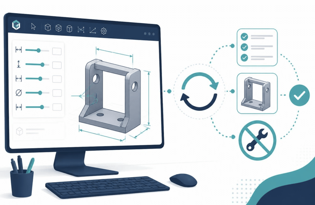
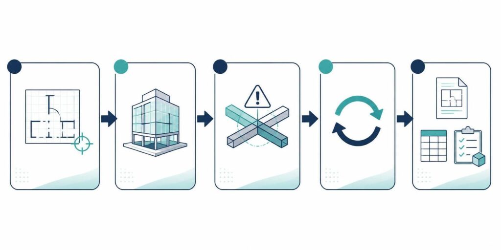
Advanced CAD designs help engineers and architects build more accurate 3D models, reduce costly mistakes, and speed up teamwork. They also let you test ideas with simulations and improve designs before anyone starts construction. If you want advanced results, focus on a simple workflow: plan your design intent, build clean parametric geometry, assemble with constraints, then export for documentation and collaboration.
What Are Advanced CAD Designs (and Why They Matter)
Advanced CAD is more than “3D drawing.” It uses smarter modeling tools that make changes easier and keep designs consistent.
With advanced CAD designs for engineering & architecture, you can create models that match real-world needs and support collaboration across teams.
Benefits You Can Expect Right Away
Advanced CAD designs can improve quality and speed from day one. You also get better handoffs between design, engineering, and construction teams.
Here are the most practical benefits:
- More accurate models that reduce rework
- Faster updates with parametric design
- Clear drawings and documentation from the model
- Better collaboration with BIM workflows
- Early risk checks using analysis tools
To understand BIM and model-based workflows, review guidance from buildingSMART and Autodesk:
Cutting-Edge Tools to Look For
Advanced CAD often includes features that help you move from concept to buildable plans. Look for tools that support modeling, rendering, and simulation.
Common advanced features include:
- Parametric modeling (design rules that update automatically)
- 3D modeling + clean surface workflows
- Rendering for better client review
- Simulation and performance checks (loads, heat, airflow)
- BIM integration to reduce clashes and version confusion
If you want a clear overview of how CAD and BIM relate, this resource is helpful:
Step-by-Step Workflow (Actionable and Simple)
You can apply this workflow to most engineering and architecture projects. It’s designed to keep your model stable as requirements change.
Step 1: Set your design intent with parameters
Start with key dimensions, spacing rules, thickness rules, and clearances. Use parameters so updates flow through the model.
Step 2: Build geometry that is “export-ready”
Create clean solids or surfaces with consistent units. Avoid tiny messy details that can break later exports.
Step 3: Use robust references for features
Reference stable datums like planes, axes, and named sketches. This helps your model update without failing.
Step 4: Assemble like a system, not a pile of parts
Constrain components based on real-world fit. Check for interference and motion limits when needed.
Step 5: Test with the right simulation tools
Run quick checks before you finalize drawings. Use stress, thermal, or other tools that match your project goals.
Step 6: Generate drawings and handoff packages
Pull consistent dimensions, schedules, and documentation from the model. Use a standard template so your deliverables stay uniform.
Step 7: Sync with BIM for coordination
If your project uses BIM, keep model data aligned. This reduces miscommunication and helps clash detection.
For BIM concepts and collaboration, see:
How to Get Results Faster
If you want better outputs, don’t just learn buttons—build a repeatable system. When your workflow is stable, every new project starts faster and with fewer mistakes.
Start today by choosing:
- one parametric template to reuse,
- one documentation template for consistent drawings,
- one export standard for collaboration.
Then keep improving your workflow based on what breaks (and fix those weak points first).